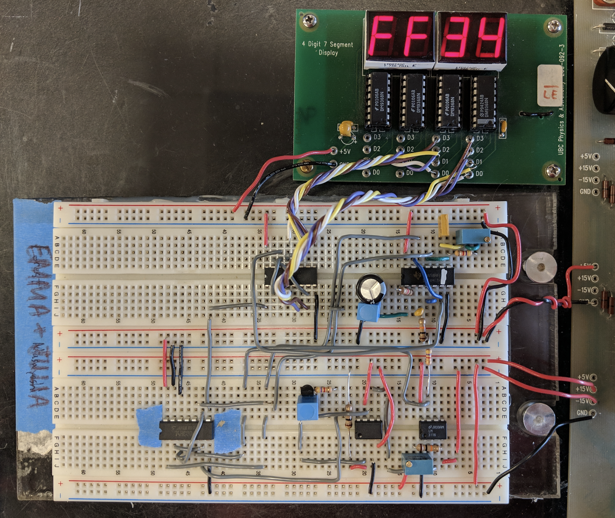
An ADC Deep-Dive
The one where Emma & Julia face the toughest debugging challenge of their university careers to date (don't tell them about Robot Summer; they don't need to know about that yet).

From sound to power to luminosity, analog signals can be found everywhere in the natural world. However,
in order for these signals to be stored, loaded and analyzed by computers, we require a means to
discretize them into binary values that represent their magnitudes.
Our analog-to-digital converter uses an analog-to-time converter to do exactly this. From a technical
standpoint, the process can be generalized as follows: a series of "gate pulses" are generated with a
frequency that is proportional to the magnitude of the system input voltage, and the rising edge of one
of these gate pulses triggers a constant-frequency clock pulse, hooked up to a counter, to quantify the
number of clock pulses that fit under a gate pulse. This number can be converted to represent the
magnitude of the input signal, and the result from that becomes the output of the system, updating with
each new gate pulse.
